
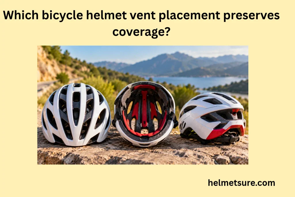
Which Bicycle Helmet Vent Placement Preserves Coverage?
Why Vent Openings and Helmet Coverage Are Different Design Measures
Bicycle helmet vent openings and head coverage are different measures because vents interrupt material within a helmet, while the protective-liner perimeter determines how far its structure extends around the head.
How the protective liner and lower helmet rim determine head coverage
The bicycle helmet’s protective liner and lower rim determine its observable anatomical coverage by defining where protective material extends around the correctly positioned head.
Locate the energy-absorbing liner, commonly expanded polystyrene, or EPS foam. Follow its lower boundary at the front, along both sides, and around the rear. That boundary helps you assess the helmet’s anatomical extent.
Why a vent surrounded by impact-absorbing foam differs from an exposed helmet edge
A vent surrounded by impact-absorbing foam is an internal opening within the helmet’s protective construction, while an exposed helmet edge marks the end of that construction.
Imagine an opening above a front foam band. The opening interrupts material locally, but the band still extends across the forehead. Shortening that band upward changes the lower coverage boundary itself.
Preserving the perimeter does not make a vent equivalent to solid foam. It identifies a geometric distinction; the effect on an impact remains a separate testing question.
| Feature | What it tells you | What it cannot establish |
|---|---|---|
| Vent inside the liner perimeter | Material is interrupted locally | Impact attenuation at that opening |
| Lower protective-liner boundary | Where the protective construction ends | A comparative safety score |
| Outer-shell extension | Where the shell reaches | Whether protective foam extends equally far |
| Soft padding or retention cradle | Where comfort or fitting components sit | Additional energy-absorbing coverage |
Why vent count alone cannot establish whether a helmet provides adequate protection
Vent count cannot establish bicycle helmet protection because openings differ in size, position, supporting foam, shell construction, and measured impact response.
Ten narrow openings and ten broad openings describe different material arrangements. The count says nothing about the liner beneath their edges or whether the helmet stays correctly positioned on your head.
Where Front, Side, Crown, and Rear Vents Sit Relative to Head Coverage
Front, side, crown, and rear bicycle helmet vents relate differently to the forehead, temples, upper head, and occipital region, so each opening must be evaluated against the surrounding liner and protective perimeter.
Front intake vents positioned above the protective forehead rim
Front intake vents positioned within the helmet above a correctly extending forehead rim can provide access for airflow without necessarily shortening the protective brow coverage.
Look beneath the intake to identify the actual front liner. A visor or shell lip may create the impression of a low front edge while the foam ends higher.
Assess bicycle helmet coverage and fit with the helmet level in its intended position. If you tip it backward before inspecting the opening, you have changed the very coverage you are trying to evaluate.
Side vent openings and their relationship to temple-area liner coverage
Side vent openings must be assessed against temple-area liner coverage because the presence of an opening does not reveal whether protective material adequately extends around the side of the head.
Trace the liner beside the temporal region on both sides. Determine whether a side aperture sits above the lower boundary or extends into it. Also distinguish protective material from straps running across otherwise exposed areas.
Crown vents positioned within the upper impact-absorbing structure
Crown vents lie within the upper helmet structure and can interrupt foam locally without necessarily changing the lower perimeter that determines forehead, side, and rear coverage.
An overhead photograph therefore answers only part of the question. It shows upper openings and the material between them, but not how low the liner sits on the wearer.
Treat crown geometry as a structural feature requiring complete-helmet validation. Moving vents upward does not automatically make a helmet safer.
Rear exhaust vents and their relationship to occipital coverage
Rear exhaust vents can sit above the protective occipital liner perimeter, so the rider must inspect the actual lower rear liner rather than infer coverage from outlet placement.
Find the foam beneath and beside the exhaust openings. Then identify the retention cradle separately: a cradle reaching low around the back of the head is not the same as protective liner reaching that far.
The coverage map is straightforward: inspect below front intakes, beside side openings, around crown apertures, and beneath rear outlets. At each position, follow the protective material rather than the accessory outline.
How Vent Size and Spacing Affect Helmet Liner Continuity
Vent size and spacing affect the remaining liner geometry because opening dimensions, foam bridges, and shell construction determine the material arrangement available to respond to localized loading.
How wider ventilation openings reduce the local area occupied by protective foam
Wider helmet vents generally change the local area occupied by protective foam, leaving a different distribution of material around the opening.
If the surrounding design stays unchanged, enlarging an aperture removes foam from that local area. Across different helmets, however, designers may also change thickness, curvature, materials, or reinforcement.
Why foam bridge spacing and liner thickness influence impact response around vents
Foam bridge spacing and liner thickness can influence localized bicycle helmet impact response because they affect the material geometry and available deformation distance around ventilation openings.
A foam bridge is a section of liner separating adjacent openings. Its behavior depends on the assembled structure, including the foam properties and loading direction—not simply its visible width.
Bland, McNally, and Rowson’s 2018 testing of ten helmet models found that vent configuration, shell thickness, and curvature influenced effective stiffness at the tested temporal location. That finding supports evaluating interacting design variables; it does not identify a universally safest bridge spacing.
How shell construction and integrated reinforcement interact with vented foam structures
Outer-shell construction and integrated reinforcement can alter the impact behavior of vented helmet foam by affecting load distribution and the way the assembled structure deforms.
The shell, its connection to the liner, and any internal reinforcement operate together. A visible rib or a manufacturer-described reinforcement feature therefore needs construction-specific interpretation.
Without verified model documentation, avoid assuming what lies beneath the surface. Even a documented reinforcement feature requires performance evidence before it supports a claim of comparative protection.
Why visual foam continuity cannot replace impact testing
Visible foam continuity cannot replace impact testing because an apparently intact liner does not reveal the helmet’s acceleration response under specified impacts.
Inspection can show where material remains and reveal some damage. Instrumented testing measures what happens when the helmet is loaded dynamically.
How Front-to-Rear Vent Channels Provide Cooling Without Reducing Helmet Coverage
Front-to-rear bicycle helmet channels can support cooling by connecting functional front inlets with internal passages and outlets while the helmet remains in its correct protective position.
How front intake vents feed cooling air into internal helmet channels
Front bicycle helmet intakes can supply air to internal channels when the incoming relative wind and local pressure conditions support airflow through those openings.
The process begins with air entering a functional intake rather than passing over the shell. Head-relative airflow depends on travel, wind, and head orientation, so an opening’s apparent size is only one factor.
Once inside, air must reach the space near the scalp for useful local ventilation. An impressive exterior aperture does not demonstrate that route on its own.
How longitudinal airflow channels carry air toward rear exhaust openings
Longitudinal helmet channels can carry air from front inlets toward rear outlets when the internal passages remain connected and pressure conditions support through-flow.
The intended sequence is intake, internal passage, and outlet. Effective air exchange can support convective cooling and evaporative heat loss, but airflow distribution and heat transfer are different measurements.
Why additional crown openings do not always increase cooling efficiency
Additional crown vents do not necessarily increase cooling efficiency because openings with unfavorable pressure conditions or poor internal connections may contribute little fresh-air exchange.
In De Bruyne’s five-helmet study, local ventilation varied substantially, and top openings were not always useful under the tested cycling conditions. The researchers favored functional connections between front inlets and rear outlets.
These findings explain why counting upper openings can mislead. They do not prove that crown vents are ineffective in every helmet, wind direction, or riding posture.
How helmet orientation changes ventilation without justifying a higher wearing position
Helmet orientation can change the airflow reaching its vents, but cyclists should not tilt or raise the helmet out of its correct fitted position to improve cooling.
A normal change in riding posture changes the helmet’s angle to the air. Deliberately rotating the helmet backward on the head changes its protective position.
Which Bicycle Helmet Vent Layouts Balance Coverage and Cooling?
Bicycle helmet vent layouts balance coverage and cooling differently because their opening positions, supporting foam, lower protective boundaries, and internal airflow routes vary by design.
Front-to-rear channel layouts with a continuous lower protective rim
Front-to-rear channels with a continuous lower protective rim can offer a useful ventilation arrangement while retaining intended brow, side, and rear coverage in an appropriately designed helmet.
This is a reasonable layout to investigate when you want connected airflow passages. Confirm that the apparent lower band is protective liner and that it sits correctly on you.
A continuous band is a geometric observation. Its presence does not establish impact superiority over another compliant construction.
Distributed crown vents with multiple supporting foam bridges
Distributed crown vents create multiple upper openings separated by supporting foam bridges, making airflow and structural response dependent on the actual arrangement.
Check whether the upper apertures connect to useful internal routes. Assess lower coverage separately, because a very open crown can coexist with an unchanged perimeter.
Neither numerous bridges nor numerous openings provide a reliable safety ranking. Compare the finished helmet’s evidence.
Large side and rear openings near the helmet’s lower coverage boundary
Large side and rear vents near the helmet’s lower perimeter require attention to the remaining liner because their proximity to the edge can affect how the protective construction extends around the head.
Identify whether an opening is enclosed by liner or forms a notch into its lower edge. An edge opening deserves close examination, but its presence alone does not prove inadequate design.
Compare the resulting fitted coverage and relevant testing. Do not reject every large outlet solely because it is large.
Minimal-vent designs with broader uninterrupted shell and liner surfaces
Minimal-vent helmets can have broader uninterrupted shell and liner surfaces, but that visual characteristic alone does not establish superior impact protection or adequate thermal comfort.
Some less-open designs still use substantial internal channels. Mukunthan’s study found that channel configuration mattered when comparing the tested closed helmets.
Judge actual comfort and available thermal evidence rather than assuming that all minimal-vent helmets perform alike.
| Layout | Coverage check | Cooling consideration | Protection conclusion |
|---|---|---|---|
| Front-to-rear channels | Confirm the lower liner remains appropriately positioned | Look for connected intake-to-outlet passages | Requires complete-helmet evidence |
| Distributed crown vents | Inspect the lower perimeter separately from upper openings | More openings may not improve local exchange | Bridge appearance cannot rank safety |
| Large side or rear openings | Inspect liner beside and beneath each aperture | Performance depends on functional flow paths | Opening size alone is insufficient |
| Minimal vents | Identify actual liner extent beneath the shell | Internal channels can still matter | Fewer vents do not establish superiority |
What Helmet Safety Tests Reveal About Vent Placement and Coverage
Helmet safety testing establishes performance under defined impact requirements, including eligible vent sites, but it does not prove that every certified vent layout protects identically at all head locations.
Why CPSC impact testing can include vent openings within the designated impact region
CPSC impact testing can include bicycle helmet vents because ventilation openings and other features within the designated test region are valid impact sites.
Under 16 CFR § 1203.17(b)(2), eligible sites include vents, fasteners, and other helmet features. Test personnel select permitted configurations intended to provide a severe test; vents are not categorically exempt.
How the CPSC impact test line limits which lower helmet regions are directly tested
The CPSC impact test line limits eligible impact-center placement to points on or above the prescribed line, so testing under that procedure does not directly cover every lower helmet location.
The helmet positioning index establishes its specified position on the test headform. The prescribed procedure then locates the impact test line. This is a laboratory reference, not a visible boundary separating protective from nonprotective material.
Harlos and Rowson’s impact-location research identified commonly damaged front and rear rim regions below that line and found location-dependent performance in tested models. Such findings support attention to lower regions without proving that all lower rims perform poorly.
Why passing certification does not establish identical protection across all vent layouts
Passing applicable bicycle helmet certification confirms compliance with specified requirements, but it does not establish identical impact responses among different vent arrangements or helmet models.
For the CPSC impact procedure, peak headform acceleration must not exceed 300 g. The standard also addresses other requirements, including retention and positional stability.
How independent multi-location impact ratings strengthen comparison between certified helmets
Independent multi-location impact ratings strengthen helmet comparisons by measuring complete-helmet responses under additional standardized scenarios rather than relying on vent position or certification status alone.
Virginia Tech’s bicycle STAR system uses 24 impacts across six locations and measures linear acceleration and rotational velocity. Its weighted score compares tested helmet performance; lower numerical scores indicate better performance within that system.
| Evidence | What it establishes | Main limitation |
|---|---|---|
| CPSC impact testing | Performance against specified impact requirements, with eligible vents included | Does not strike every possible location |
| CPSC positioning and retention tests | Performance under prescribed stability and retention procedures | Does not establish fit on your individual head |
| Independent STAR results | Comparative complete-helmet performance in additional scenarios | Does not isolate vent placement or guarantee an individual outcome |
| On-head inspection | Actual worn position, visible coverage, and stability | Cannot measure impact attenuation |
How to Check Whether Vent Placement Preserves Coverage on Your Head
Cyclists can evaluate whether bicycle helmet vents preserve intended coverage by wearing the helmet correctly and checking the protective brow, side, and rear liner boundaries while confirming stable retention.
How to verify forehead coverage without tipping the helmet backward
Forehead coverage should be checked with the bicycle helmet level and positioned according to the manufacturer’s instructions, not tilted backward to gain ventilation.
Use a mirror to identify the front liner rather than the visor. NHTSA’s general fitting guide places the front rim about two finger widths above the eyebrows; follow the model’s instructions for its intended position.
If correct positioning cannot be achieved comfortably, reconsider the size or head-shape match.
How to inspect side-liner coverage around the temple region
Side-liner coverage should be inspected by checking where the helmet’s protective material extends around the temples while the helmet remains correctly positioned.
Use side views or ask someone to help. Trace material above and below the side apertures, checking both sides for an unevenly seated helmet.
Record what you can observe: liner extent, openings, and worn position. Avoid translating these observations into an untested impact score.
How to assess rear protective coverage beneath exhaust vents
Rear protective coverage should be assessed by locating the lower occipital liner beneath the helmet’s exhaust openings while distinguishing protective foam from retention hardware.
Check from behind while maintaining your normal wearing position. Identify which component reaches lowest: shell, liner, cradle, or strap.
Compare helmets without moving either one away from its correct position to make its rear profile appear deeper.
How to test whether strap adjustment keeps the helmet stable over covered regions
Proper strap and retention adjustment should keep the bicycle helmet stable over its intended protective regions without allowing it to shift excessively or roll backward.
Follow the manufacturer’s adjustment sequence, then gently move your head and check whether the helmet slips. Recheck its position after adjustment.
Five Checks Before Accepting the Fit
If adjustment cannot produce stable, comfortable positioning, try another size or model.
Which Vent-Placement Warning Signs Should Override a Cooling Advantage?
Ventilation advantages should not justify using a bicycle helmet that fails to maintain intended coverage, contains damaged protective components, fits unstably, or lacks verifiable required safety compliance.
When a raised front or rear rim leaves intended protective regions exposed
A raised front or rear protective rim is a rejection concern when the bicycle helmet cannot cover its intended forehead or occipital regions in the manufacturer’s correct wearing position.
First rule out incorrect adjustment. If the helmet still sits improperly, compare another size or shape. Do not compensate for one exposed region by tilting the helmet so another loses its intended coverage.
When cracked, damaged, or deteriorated foam makes vented helmet protection unreliable
Cracked, crushed, or deteriorated protective foam makes a vented bicycle helmet unsuitable because damage can undermine the liner’s intended response to impact.
Inspect around openings and bridges as well as other accessible surfaces. Stop using a helmet with compromised protective components and follow its replacement instructions.
When achieving better airflow requires an unsafe helmet position or oversized fit
A bicycle helmet is unsuitable when better airflow requires raising it, tipping it backward, or choosing an oversized fit that cannot retain intended protective coverage.
An intentionally loose gap is not a substitute for a functional ventilation channel. Compare cooling only after establishing the correct size and wearing position.
When missing applicable certification prevents verification of minimum impact requirements
Missing verifiable applicable safety compliance prevents confirmation that a bicycle helmet meets the prescribed minimum requirements for its intended market and activity.
For a U.S.-market bicycle helmet, check the required CPSC compliance labeling and identifiable model information. Elsewhere, verify the requirements applicable to the intended market and use.
| Warning sign | Corrective action |
|---|---|
| Intended coverage cannot be maintained | Refit, then change size or model if necessary |
| Cracked or crushed protective components | Stop use and follow replacement instructions |
| A relevant impact despite no visible damage | Follow the manufacturer’s post-impact guidance |
| Cooling requires loose or tilted positioning | Evaluate another helmet in the correct position |
| Required compliance cannot be verified | Obtain authoritative evidence before use |
Which Vent Placement Should Riders Prioritize for Coverage and Comfort?
Riders should prioritize a vented helmet that meets applicable requirements, fits securely over intended protective regions, and has suitable complete-helmet impact evidence before deciding which airflow arrangement they prefer.
Why verified protective coverage and stable fit take priority over maximum ventilation
Verified intended coverage and stable fit take priority over maximum ventilation because the helmet must remain correctly positioned over the head regions it was designed to protect.
An attractive vent layout cannot correct a poor head-shape match or displaced liner. Eliminate unsuitable candidates before comparing cooling features.
When an effective front-to-rear airflow layout is a suitable choice among adequately protective helmets
An effective front-to-rear airflow layout is a suitable preference when the bicycle helmet already meets relevant safety requirements, covers intended regions, and fits correctly.
Why independent impact performance is a stronger final discriminator than vent location alone
Independent complete-helmet impact performance provides stronger comparative evidence than vent location alone because it measures tested helmet response instead of inferring protection from visible openings.
Where comparable results exist, use them alongside fit, condition, and intended use. A well-rated helmet still needs to fit you correctly.
| Priority | Verification | Decision |
|---|---|---|
| 1. Applicable compliance | Confirm intended use and required conformity | Exclude candidates with unverified mandatory suitability |
| 2. Fit and anatomical coverage | Inspect brow, side, and rear liner extent in the correct position | Keep models that fit securely |
| 3. Equipment condition | Check damage and relevant impact history | Exclude compromised equipment |
| 4. Complete-helmet impact evidence | Review relevant independent results when available | Compare measured performance |
| 5. Ventilation | Assess functional openings, channels, and comfort | Choose acceptable cooling among suitable helmets |
| 6. Layout preference | Compare the remaining vent arrangements | Treat location as a conditional design choice |
An interior vent can preserve intended anatomical coverage when it does not displace the lower protective-liner boundary. No single vent arrangement guarantees superior impact protection. Compare actual, appropriately compliant helmets for fitted coverage, stable retention, condition, relevant independent testing, and acceptable ventilation before choosing.
Frequently Asked Questions
Do fewer vents automatically provide better impact protection?
No. Vent count does not establish liner geometry, shell construction, fit, compliance, or complete-helmet impact response. Compare the actual helmets and their relevant evidence.
Can an internal vent preserve forehead coverage?
Yes. A vent positioned above a correctly extending protective forehead rim may interrupt material locally without raising the lower liner boundary. Helmet-level performance still requires testing.
Are crown vents safer than side or rear vents?
No universal location ranking is supported. Opening size, surrounding foam, shell construction, lower perimeter, impact site, and complete-helmet test results all matter.
Does a low rear retention cradle provide protective foam coverage?
Not necessarily. The cradle is a fitting component. Inspect the actual energy-absorbing liner separately to determine where protective material ends.
Which ventilation layout is usually worth investigating?
A front-to-rear arrangement with functional intakes, connected channels, and outlets can be useful when the helmet also provides correct fitted coverage, compliance, condition, and complete-helmet evidence.
Can I tilt the helmet backward to expose the front vents?
No. Evaluate ventilation only while wearing the helmet in its intended position. If cooling is unacceptable in that position, compare another suitable helmet.
What best shows that a vent preserves anatomical coverage?
Select the strongest answer.
Sources and References
All 10 sources retained from the supplied article.
- R1.CPSC: Bicycle Helmets Business Guidance — Requirements, positioning, impact testing, labeling, and post-impact warnings.
- R2.16 CFR § 1203.17: Impact attenuation test — Official regulatory text, including eligible vent impact sites.
- R3.Bland, McNally, and Rowson (2018): Differences in Impact Performance of Bicycle Helmets During Oblique Impacts — Complete-helmet testing and interacting construction variables.
- R4.Harlos and Rowson: The range of bicycle helmet performance at real world impact locations — Real-world damage locations and location-dependent impact response.
- R5.De Bruyne et al. (2012): Quantification of local ventilation efficiency under bicycle helmets — Five-helmet tracer-gas study of local air exchange.
- R6.Mukunthan et al. (2019): Thermal-Performance Evaluation of Bicycle Helmets for Convective and Evaporative Heat Loss at Low and Moderate Cycling Speeds — Thermal-manikin evaluation under defined conditions.
- R7.Virginia Tech Helmet Lab: Bicycle Helmet Ratings — Complete-helmet STAR methodology and ratings.
- R8.NHTSA: Fitting a Bicycle Helmet — General wearing-position guidance.
- R9.Bicycle Helmet Safety Institute: Helmet Fitting Checklist — Practical fit and stability checks.
- R10.Bicycle Helmet Safety Institute: When Should I Replace My Bicycle Helmet? — Impact damage and replacement considerations.