
How Is the Helmet Constructed?
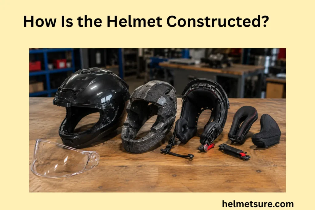
A helmet is constructed as a layered assembly in which an outer shell, impact-management liner, wearer-contact components, retention hardware, and any openings or fit mechanisms are physically integrated to form the finished helmet.
The familiar outside-to-inside picture—shell, impact liner, padding, then the head—is a useful starting point, but it is not a universal recipe. Bicycle, motorcycle, snow, equestrian, industrial, military, and other helmets can use different materials, suspension arrangements, attachment methods, and opening geometries. What makes each product a helmet construction is not one material by itself, but the way its components are shaped and connected as an assembly.
This guide follows that assembly from the outer shell inward. It explains the structural liner, the shell-to-liner interface, comfort and fit components, the retention path, and the integration of vents and openings before comparing broad manufacturing relationships.
Helmet Construction as a Layered System Rather Than a Single Protective Piece
Helmet construction is a layered assembly in which structural protective components and wearer-interface components perform different jobs while remaining parts of one physical system.
The structural group may include an external shell and an impact-absorbing liner, multiple structural liners, an engineered energy-management structure, or—in some industrial head protection—a shell supported away from the head by a suspension. The wearer-interface group can include comfort padding, a headband or cradle, adjustment hardware, and parts that manage contact with the head. A retention subsystem connects the assembly to the wearer, while vents and other openings intersect the geometry of the surrounding layers.
“Layered” therefore describes physical organization, not a fixed number of parts. Some layers are permanently joined; others nest together, attach mechanically, or are designed to be removable. The construction can be understood only by identifying both the components and the interfaces between them.
How the shell, impact liner, retention system, and internal components form one assembly
The shell, impact liner, retention system, and internal components form one helmet assembly through a combination of molded, bonded, anchored, nested, or removable interfaces whose exact design varies by helmet type.
In a common foam-lined architecture, the outside-to-inside sequence begins with the external shell, continues through an impact-absorbing or energy-management liner, and ends with comfort or fit components next to the wearer. Retention straps intersect that sequence at their anchor points rather than simply hanging from an unrelated surface. Vent openings can also pass through the shell and influence the shape of the structural liner and its internal channels.
Each interface answers a different construction question. The shell-to-liner interface determines whether the main structural layers are fused, bonded, nested, or separately assembled. The liner-to-pad interface determines how the wearer-contact layer is held in place. Retention anchors connect webbing or a suspension to defined parts of the helmet body, and openings establish geometric paths through one or more layers. Separate components become a unified assembly through these relationships.
Structural protective components versus comfort and fit components
Structural protective components form the helmet’s primary physical body, while comfort and fit components create the wearer interface and must not be confused with the impact-management liner.
The outer shell and structural impact-management components define the helmet body in many familiar designs. Beneath or within that body, softer comfort pads can form the immediate contact surface, absorb perspiration, reduce pressure points, or cover harder internal features. An adjustable cradle, headband, dial, or related framework can change the internal fit geometry without becoming the impact liner.
Fit systems and comfort components still belong to the finished construction. Their location, attachment points, replaceability, and interaction with the structural body affect how the assembly is put together. They simply perform a different construction role from the principal impact-management layer. Readers evaluating how those components should interface with an individual head can treat helmet fit as a separate question.
Helmet Component Roles and Physical Positions
| Component | Physical Position | Construction Role | Do Not Confuse With |
|---|---|---|---|
| Outer shell | Exterior | Forms the helmet’s outside structural layer | Comfort padding |
| Impact liner | Beneath or inside the shell in applicable designs | Forms the main structural energy-management layer | Removable comfort liner |
| Comfort padding | Closest to the wearer in many designs | Creates the contact and cushioning interface | Impact liner |
| Fit system | Internal adjustable assembly where fitted | Adjusts how the helmet interfaces with the wearer | Structural liner |
| Retention system | Anchored to the helmet assembly | Connects the helmet assembly to the wearer | Fit padding |
How Is the Helmet’s Outer Shell Constructed?
The helmet’s outer shell is the external structural layer whose material, geometry, thickness, finish, and manufacturing relationship with the liner vary across helmet constructions.
Manufacturers form the shell around a three-dimensional design that can include a crown, lower edges, coverage extensions, vent cutouts, attachment zones, and surface features. Depending on the helmet, the shell may be a relatively thin formed skin integrated with a liner, a more substantial independently formed hard shell, a fiber-reinforced composite structure, or one region within a hybrid assembly.
Material and thickness matter only within that complete context. A shell specification does not reveal how the shell meets the liner, how openings are reinforced or surrounded, where retention anchors connect, or how the design is intended to be tested. The shell is the assembly’s exterior layer, not a self-contained substitute for the helmet.
How the outer shell creates the helmet’s external form and surface layer
The outer shell creates the helmet’s external form by defining the outside geometry, surface, edges, and openings around which the remaining construction is organized.
Its crown establishes the principal exterior curvature. Its perimeter establishes where the exterior layer ends around the brow, sides, and rear, while category-specific extensions or facial coverage can add further surfaces. Vent apertures, accessory interfaces, trim boundaries, and retention-related attachment zones may also be formed into or coordinated with the shell geometry.
That geometry becomes an interface surface for underlying components. A structural liner may follow the shell’s inner contour, fill part of its volume, or meet it at designed contact regions. Edge treatments can cover or finish the junction between shell and liner. Openings may continue into liner passages, and anchor locations may require space within the underlying assembly. Shell geometry therefore establishes the external form around which other parts are organized.
How shell material and thickness can vary between helmet constructions
Shell material and thickness vary between helmet constructions because different manufacturing systems use the shell in different physical forms and relationships with the underlying structure.
Polycarbonate, ABS, and fiber-reinforced composites are examples of shell material classes found in documented helmet designs, not a universal list for all helmets. A bicycle helmet may use a formed polycarbonate shell that is permanently fused to a foam liner during an in-mold process. A snow helmet may combine an ABS hard-shell region with an in-mold lower region. Other helmet categories and products can use different polymers, fibers, resins, forming processes, or layered arrangements.
Thickness is equally construction-specific. A thin shell integrated with a supporting liner and a separately formed rigid shell are not interchangeable merely because both are called shells. Their dimensions, stiffness, edge details, and liner relationships belong to different architectures. Even within one material family, formulation, forming, curvature, and local geometry can vary.
Giro’s documentation provides two deliberately narrow examples. Its Tremor bicycle helmet describes a polycarbonate lower shell permanently fused to the liner, while its Tor snow helmet describes a hybrid construction that combines a ventilated hard-shell upper with an in-mold lower shell and sidewalls. These manufacturer-defined examples show how material selection follows the assembly method; they do not establish an industry-wide taxonomy or a safety ranking.
No shell material or thickness is universally “best” in isolation. Nor does more shell material automatically mean more protection. Certification and performance conclusions require the relevant complete-helmet tests and documentation, not a visual or material comparison.
How Is the Impact-Absorbing Liner Built Beneath the Shell?
The impact-absorbing liner is a structural energy-management layer positioned within the helmet assembly, although its material, thickness, geometry, and relationship with the shell vary by helmet design.
In many conventional helmets, this layer is a molded cellular foam body whose external geometry follows part of the shell and whose internal geometry helps define the space around the wearer. Other designs may use more than one liner region, different foam types, engineered cellular or lattice-like structures, or a suspension architecture instead of the same continuous foam arrangement.
A recent peer-reviewed review describes traditional liner materials including expanded polystyrene, expanded polypropylene, polyethylene, and polyurethane, alongside emerging material and structural concepts. The review demonstrates variety rather than a universal specification: a material named in helmet research or in one commercial product cannot be assumed to appear in every category or model.[1]
How the impact liner forms the main energy-management layer beneath the shell
The impact liner forms the principal energy-management layer in many helmet constructions by using deformable material or engineered structure beneath the shell to manage mechanical loading.
At the construction level, a cellular foam liner is built from a volume of material containing many cells. When loaded, parts of that structure can deform, changing the way mechanical energy and force move through the assembly. An engineered geometry can pursue the same broad component role through deliberately shaped cells, columns, layers, or other structures. “Energy-management layer” describes this physical role; it is not a promise of a particular injury outcome.
The liner’s material and geometry work together. Material type, density, cell structure, molded shape, thickness distribution, segmentation, and any interfaces between liner regions can all differ. The shell-to-liner relationship also matters because the liner does not operate as an abstract sample: it occupies a specific position inside a complete helmet body.
EPS is a common example, but it is not a synonym for “helmet liner.” The research literature also discusses EPP, PE, PU, and newer structures, with some concepts remaining experimental or limited in commercial use. Each example needs helmet-category, product, or study context. The presence of foam alone does not establish how the helmet performs, and a soft internal surface should not automatically be identified as the structural liner.
Why the structural liner must be distinguished from removable comfort padding
In a conventional shell-and-foam arrangement, the structural liner sits beneath the shell and forms part of the helmet body. Comfort padding is commonly located inward of that structural layer, closer to the wearer. The comfort layer can provide a softer contact surface, while the impact liner supplies the principal deformable structural volume in that design.
NHTSA’s motorcycle-helmet materials explicitly distinguish an impact-attenuating liner from a cloth or soft comfort liner. In some designs, comfort pads are attached with tabs, hook-and-loop areas, snaps, or other removable interfaces, although the exact method must be confirmed by the manufacturer. Their removability does not make them the primary impact liner, and the structural liner should not be treated as ordinary replaceable padding.
Some internal parts can combine functions, and terminology differs among manufacturers and helmet categories. That is why documentation—not softness, color, or exterior appearance—should determine whether a component is structural, comfort-oriented, or multifunctional. Using modifiers such as “impact liner,” “energy-management liner,” “comfort liner,” and “comfort pad” keeps those roles clear.
How Are the Outer Shell and Impact Liner Joined Into One Helmet Structure?
The outer shell and impact liner become one helmet structure through an integration method such as permanent molding or fusion, bonding, mechanical nesting, or separate assembly, depending on the construction design.
The interface method is a construction attribute distinct from the materials being joined. Two helmets can name similar shell and liner materials yet arrange or connect them differently. Conversely, a broad integration concept such as “separate assembly” can be implemented with different materials and detailed attachment features.
Understanding this junction moves the explanation beyond a parts list. The shell and liner do not become a structural body merely because both are present; their contours, contact regions, edge relationships, and attachment method determine how they occupy the same assembly.
How shell and liner integration creates the helmet’s main structural body
Shell and liner integration creates the helmet’s main structural body by establishing a stable physical interface between the external shell and the internal energy-management structure.
In permanent integration, the forming or molding process joins the layers so that the shell remains attached to the liner as a combined body. In a bonded construction, an adhesive or another specified bonding system can connect separately produced parts. In a nested or separately assembled design, an independently formed liner fits within an independently formed shell and is held in its intended relationship by the product’s documented assembly features.
The relevant construction description is therefore shell + interface method + liner. It should identify not only what the two components are made from, but how their shapes meet and how that relationship is maintained. Edge finishing, localized attachment regions, intermediate layers, and shell coverage can further distinguish one implementation from another.
How molding or bonding methods change the relationship between the two layers
Molding or bonding methods change the shell-liner relationship by determining whether the two layers are formed as an integrated structure or assembled as distinct components.
An in-mold process provides a documented integrated example. Giro describes its in-mold construction as fusing a polycarbonate outer shell with an impact-absorbing foam liner. The key construction fact is the permanent shell-liner relationship created during manufacture. It does not mean that every product called “in-mold” uses identical materials, coverage, process parameters, or secondary parts.[3]
A separately assembled construction begins with independently formed primary layers and combines them later. Depending on the verified design, their relationship can involve bonding, close nesting, mechanical features, trim, or other interfaces. A generic description should stop there unless authoritative product documentation identifies the detailed attachment method; adhesives, molding temperatures, pressures, or fastening details should never be invented.
Hybrid construction prevents this comparison from becoming a false two-option taxonomy. Giro describes the Tor snow helmet’s manufacturer-defined Hybrid Construction as a hard-shell upper combined with an in-mold lower shell and sidewalls. That example places more than one shell-liner relationship within a single helmet. It illustrates physical variation, not a universal advantage in safety, weight, ventilation, or durability.
How Are Padding and Fit Components Added Inside the Helmet?
Padding and adjustable fit components are added inside the helmet as wearer-interface systems that sit alongside or over the structural liner without automatically becoming part of that liner.
These components occupy the interior left by the main structural body. Pads can cover selected contact areas, while a cradle, headband, or adjustment framework can define an adjustable internal circumference or support position. Their attachment must coexist with the structural liner, retention anchors, ventilation paths, and any removable interior pieces.
Placement and connection are construction questions; whether the assembled helmet fits a particular person is a separate evaluation. The existence of a dial, pad set, or headband does not prove correct fit, and internal components should not be modified or substituted contrary to the manufacturer’s instructions.
How comfort pads create the contact layer between the helmet and the head
Comfort pads create the helmet’s immediate contact layer by placing softer, often removable material between the wearer and the harder structural components.
In many designs, pads cover only selected regions rather than forming a continuous structural volume. Their internal-facing surface touches the wearer, while their opposite side attaches to the liner, a fit framework, a fabric carrier, or another documented interior interface. The pad’s position—not merely its softness—identifies it as part of the wearer-contact layer.
Attachment methods vary. Manufacturers may use hook-and-loop zones, tabs, snaps, pockets, or model-specific carriers, and not every pad is designed for user removal. When a pad is removable, that feature allows the contact component to separate from the assembly; it does not turn the underlying impact liner into another removable comfort part.
This distinction also sets a boundary on modification. Changing pad thickness, adding unapproved material, or relocating internal pieces can change the wearer interface and may conflict with the product instructions. Construction explains where the contact layer sits and how it attaches; helmet fit explains how the complete helmet should be evaluated on a wearer.
How adjustable fit systems are integrated without becoming part of the impact liner
Adjustable fit systems are integrated as separate internal mechanisms that alter the wearer interface while remaining mechanically distinct from the helmet’s primary impact liner.
A fit system can include a cradle, headband, dial, slider, cable, or adjustment framework. These elements attach to or sit within the structural body and change internal geometry around the head. The impact liner remains the structural energy-management component; the fit mechanism changes the position or shape of the wearer interface.
The relationship can be summarized as fit hardware → adjustable internal geometry → wearer interface. Connection points may sit on the liner, shell, suspension, or a separate internal carrier, depending on the documented design. Those attachment details affect component sequencing because the fit system must share limited interior space with comfort pads, vents, retention elements, and other parts.
The generic sport-helmet model does not cover every category. OSHA’s hard-hat guidance describes a shell-and-suspension arrangement in which the suspension and headband form major internal architecture. That arrangement reinforces the broader point: internal adjustment systems vary, and their construction should be described using category-specific terminology. A fit system should also remain distinct from the retention system, which connects the helmet to the wearer rather than merely adjusting the interior contact geometry.[4]
How Is the Retention System Connected to the Helmet?
The helmet’s retention system connects to the main structure through defined anchor points or suspension interfaces and is completed by the hardware used to secure and adjust that connection.
A strap-based system is more than a chin strap. It is a continuous construction path that begins at the helmet’s attachment locations, passes through webbing and positioning hardware, and reaches a closure. Some categories instead rely on different suspension or retention architectures, so strap count, anchor count, routing, and closure type cannot be assumed universally.
How straps and anchor points connect the retention system to the helmet structure
Straps and anchor points connect a strap-based retention system to the helmet structure by transferring the retention path from the wearer into defined attachment locations on the helmet assembly.
The webbing may route through or attach to designated interfaces associated with the shell, liner, cradle, embedded hardware, or another structural feature. The exact arrangement depends on the helmet category and model. What remains constant in the strap-based model is the relationship: strap → anchor or interface → helmet structure.
Anchors are therefore part of the construction, even when they are not externally visible. Their location must coexist with the shell-liner interface, internal padding, fit hardware, and edge treatment. Routing can also determine where straps emerge from the helmet and how they connect to adjustment hardware outside or inside the perimeter.
No universal two-point, three-point, or four-point pattern should be assumed. Some helmets use different strap geometries, and some industrial systems use adjustable suspension assemblies whose connection model differs from a typical sport helmet. Because retention hardware is structural equipment, anchors and straps should not be drilled, relocated, stitched, or replaced with unapproved substitutes.
How buckles and adjustment hardware complete the retention assembly
Buckles and adjustment hardware complete a strap-based retention assembly by joining, tensioning, and positioning the webbing connected to the helmet’s anchor points.
Starting at the helmet body, the structural sequence is anchor → strap or webbing → adjustment hardware → closure. A slider may change usable webbing length, a divider may position intersecting strap segments, and a buckle or another closure joins the open parts of the retention path. A given helmet may use only some of these components or arrange them differently.
A buckle closes the system; adjustment hardware changes strap position or tension. Keeping those terms separate makes the assembly easier to trace and prevents the closure from being treated as the entire retention system. Magnetic-assisted buckles, side-release buckles, double-D rings, and other closures are product-specific implementations rather than universal construction features.
This description is not a strap-fitting tutorial. Correct routing and adjustment must follow the manufacturer’s instructions for the specific helmet. The construction point is that closure hardware works only as the final part of an anchored retention path.
How Are Vents and Openings Integrated Without Breaking the Helmet’s Overall Structure?
Vents and other openings are integrated by designing their geometry into the shell, liner, channels, or surrounding structural features rather than treating them as holes added independently after construction.
An engineered opening has a location, shape, edge, direction, and relationship with nearby material. It may cross the shell, align with a shaped passage in the liner, or connect an inlet to an internal channel and an exhaust. The surrounding shell and liner geometry is designed with that feature present from the outset.
Vent count alone reveals little about the complete construction. Large and small openings, shallow grooves, internal channels, closable vents, and shells without through-vents can all belong to different architectures. More vents do not automatically mean better cooling or weaker structure, and fewer vents do not automatically mean the reverse.
How vent openings pass through or reshape shell and liner sections
Vent openings can pass through or reshape shell and liner sections, making each opening part of the geometry of the layers and internal channels surrounding it.
At the exterior, an inlet or exhaust interrupts or reshapes the shell surface. Beneath it, the liner may contain a corresponding aperture, recess, groove, or channel. When these features align, they form an integrated path through the assembly rather than two unrelated holes.
The opening geometry can influence several interfaces at once. The shell must end or curve around its perimeter, the liner must provide the intended internal passage, and comfort or fit components must avoid blocking the designed path where the product architecture requires airflow. Edge features, covers, meshes, shutters, or other components may add further interfaces when documented for a specific design.
Not all helmets use through-vents or the same inlet-and-exhaust model. Some constructions use different shell coverage, suspension spacing, adjustable apertures, or limited openings. Vent dimensions and counts should therefore be stated only for a named helmet when the figures help explain that product; they are not universal quality metrics. User-drilled or enlarged holes are not equivalent to manufacturer-engineered openings and should never be presented as such.
Why ventilation geometry becomes part of the helmet’s overall construction design
Ventilation geometry becomes part of helmet construction because openings, channels, surrounding material, and layer interfaces must coexist within the same finite shell-and-liner structure.
A vent layout determines where the shell and liner are interrupted or reshaped. Internal channels determine how the available liner volume is distributed around those passages. Attachment zones for fit hardware, pads, retention parts, and optional features must then coexist with the remaining surfaces. Ventilation is consequently an architectural constraint and interface problem, not an isolated specification.
Giro’s Merit bicycle helmet offers a scoped example: its documentation describes external vents combined with channels in an EPS foam liner. This supports the construction relationship—outside opening aligned with internal liner geometry—without turning the manufacturer’s airflow claims into a general safety or performance conclusion.
How Do Different Helmet Construction Methods Change the Assembly?
Different helmet construction methods change the assembly by changing when, where, and how the shell, liner, and secondary components are formed and connected.
The primary method also influences what attachment surfaces remain available for padding, fit hardware, retention anchors, vents, trim, and other components. Two helmets with similar external silhouettes can therefore use different hidden interfaces and component sequences.
Integrated shell-and-liner construction versus separately assembled layers
Integrated shell-and-liner construction forms or permanently joins the primary layers during manufacture, while separately assembled construction brings independently formed shell and liner components together later in the assembly process.
Giro’s in-mold description supplies a clear integrated example: a polycarbonate outer shell is fused to the helmet’s impact-absorbing foam liner. In that specific bicycle-helmet implementation, the fusion step establishes the principal shell-liner relationship. Other manufacturers or helmet categories may use the same generic label differently, so the exact material and process remain source-specific.
In separately assembled construction, the shell and liner begin as independently formed components and are combined by the design’s specified nesting, bonding, mechanical, edge, or intermediate interfaces. The parts can remain identifiable within the finished assembly. “Separately assembled” says when and how the layers meet; it does not mean that the helmet is structurally inferior.
Hybrid construction adds a third model. Giro’s Tor snow helmet combines a hard-shell upper with an in-mold lower shell and sidewalls. The helmet therefore contains distinct construction relationships in different regions. The term and its exact implementation are manufacturer-specific, and the example does not establish a general ranking for protection, durability, weight, or ventilation.
Construction Methods and Layer Relationships
| Construction Relationship | What Happens During Assembly | Shell-Liner Relationship | Necessary Qualification |
|---|---|---|---|
| Integrated / in-mold example | Shell and liner become permanently joined during the manufacturing process | Layers function as a physically integrated body | Attribute the exact process and terminology to a verified source |
| Separately assembled | Shell and liner are formed separately before being combined | Distinct parts remain identifiable within one assembly | “Separate” does not mean structurally inferior |
| Hybrid | More than one construction relationship appears in the same helmet | Hard-shell and integrated regions can coexist | Treat proprietary implementation as manufacturer-specific |
How different assembly methods change the relationship between shell, liner, and internal components
Different assembly methods change how the shell, liner, pads, fit hardware, retention components, and openings attach to or occupy the finished helmet structure.
The primary structure establishes the surfaces and spaces available to later components. A permanently integrated shell and liner may present one combined interior body for pad, cradle, or retention interfaces. Separately formed components may introduce edges, gaps, fasteners, bonding areas, or trim relationships that affect the next assembly steps. A hybrid method can create more than one kind of attachment environment within the same helmet.
This can be read as a dependency: primary construction method → available interfaces → secondary-component integration. Comfort pads need a contact or carrier surface. Fit hardware needs attachment points and clearance. Retention anchors need a defined path into the helmet body. Openings and channels need space within both the primary layers and the internal layout.
Component presence is not the same as component integration. Two helmets may both show a shell, foam liner, dial, pads, straps, and vents while using different hidden anchor points, bonding areas, or sequencing. Detailed claims about those internal relationships require manufacturer specifications, patents, authoritative teardown evidence, or peer-reviewed research. Assembly complexity and visible part count do not, by themselves, establish quality.
How Do All the Helmet Components Form the Finished Assembly?
The finished helmet assembly combines its shell, structural liner, wearer-interface components, retention system, and openings through defined physical relationships that preserve each component’s distinct construction role.
From the outside inward, the shell defines the external form, edges, and primary openings. The impact liner or another energy-management architecture occupies the structural interior. The shell-liner interface turns those principal components into a main body. Pads and fit hardware create the wearer interface, retention parts establish a connected path to the wearer, and vents intersect the geometry of the layers around them.
That sequence is a conceptual map, not a claim that every helmet has identical anatomy. Exact materials, layer counts, suspension systems, anchor patterns, ventilation layouts, and integration methods vary by category and model. The stable idea is that each part has both a role and a relationship to the surrounding assembly.
Shell, liner, fit components, retention system, and vents as one integrated structure
The shell, liner, fit components, retention system, and vents form one integrated helmet structure because each component occupies a defined position and connects physically or geometrically with the surrounding assembly.
The external shell supplies the outer surface around which the helmet is organized. Inside it, an impact liner, multiple liners, an engineered structure, or a category-specific suspension provides the principal structural interior. Their junction creates the main body. Comfort pads or a headband then form wearer-contact regions, and a fit mechanism may adjust that internal interface without becoming the impact liner.
Retention intersects the assembly through its anchors or suspension interfaces and continues through webbing, adjusters, and closure hardware where a strap-based system is used. Ventilation intersects it geometrically: shell openings align with liner openings or channels, while surrounding components occupy the remaining internal space. These subsystems are integrated because they depend on shared surfaces, volumes, and attachment points.
The broad roles are recognizable across many designs, but the implementation is not universal. A bicycle helmet with a fused polycarbonate shell and EPS liner, a snow helmet with hybrid shell regions, a motorcycle helmet with distinct impact and comfort liners, and an industrial hard hat with shell-and-suspension architecture should not be forced into one identical exploded view.
Why helmet construction should be understood as component interaction rather than one material alone
Helmet construction should be understood as component interaction rather than one material alone because the finished structure depends on how different layers, hardware, interfaces, and openings are arranged and connected.
A material list can identify what selected parts contain, but it cannot show shell geometry, liner shape, shell-to-liner attachment, pad interfaces, retention anchorage, fit-system placement, or ventilation channels. A complete construction description therefore combines material + geometry + interface.
Material properties still matter. They help define what a shell, liner, strap, pad, or fitting can be and how it can be manufactured. But material selection and construction architecture are related concepts, not interchangeable ones. NHTSA’s whole-system interpretation for motorcycle helmets makes the boundary especially clear: overall design and construction determine the result of complete-helmet requirements, rather than each test belonging to one component alone.
Understanding the assembly explains what construction is; evaluating the other helmet buying factors explains how construction fits into a complete helmet choice. A helmet is ultimately constructed as a system of materials, components, geometries, and interfaces assembled into one structure.
Frequently Asked Questions About Helmet Construction
Short answers covering layered construction, shell and liner roles, integration, fit components, retention, vents, and complete-system boundaries.
Is a helmet one protective piece?
No. It is an assembly of structural layers, wearer-interface components, retention hardware, openings, and attachment relationships.
What does the outer shell do?
It creates the external form and surface layer, supports geometry, and works with the liner and complete assembly.
Is comfort padding the impact liner?
No. Comfort padding creates the wearer-contact layer; the structural impact liner is the principal energy-management layer beneath the shell.
How are shell and liner joined?
Methods vary. They may be molded in an integrated process or produced separately and joined through designed interfaces.
Are fit systems part of the impact liner?
No. They are integrated wearer-interface components that refine position and contact without becoming the structural crush layer.
How is the retention system attached?
Webbing connects through anchor points to the helmet structure, then adjusters and a buckle complete the restraint assembly.
Do more vents automatically mean better construction?
No. Vent geometry is one construction choice; appearance or vent count alone cannot establish tested performance.
Can construction method alone rank helmet safety?
No. Labels describe assembly relationships, while tested performance depends on the complete helmet under the applicable standard.