
How Does a Bicycle Helmet Shell Support a Visor?
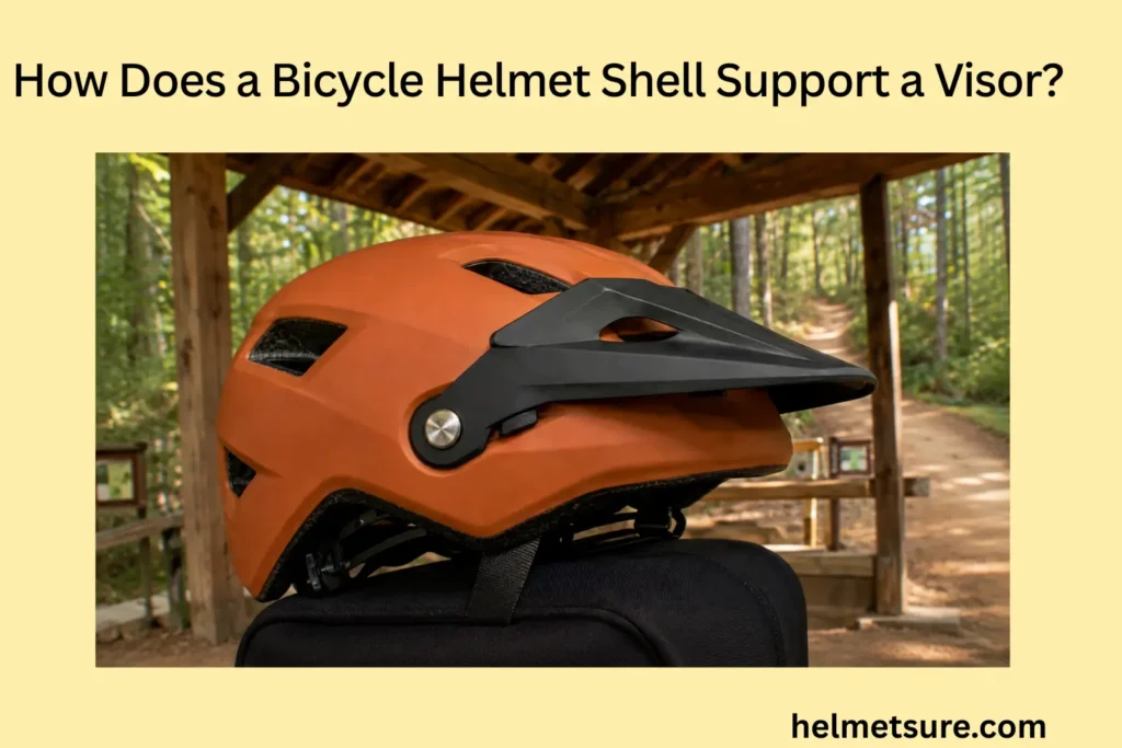
A bicycle helmet shell supports a visor through designed mounting points that locate and retain it, while surrounding helmet structure carries its weight and wind loads so the visor remains positioned during normal use.
The exact support architecture varies by helmet. Some visors use molded pins, tabs, slots, screws, clips, snaps, pivots, or hook-and-loop interfaces; others combine several features. Here, “shell” refers to the helmet-side mounting region and surrounding structure, not necessarily only the thin visible outer skin.
Use only a visor and mounting hardware approved for the exact helmet model. Do not drill, cut, glue, relocate, or improvise visor mounts unless the helmet manufacturer explicitly authorizes that modification. This page explains mechanical support; it cannot certify a modified helmet or determine whether a damaged helmet remains protective.
Visor Support as a Shell-Attachment Function Rather Than Part of the Helmet’s Main Impact Structure
Visor support is primarily an attachment and positioning function in which designed helmet mounting features hold the visor rather than making it part of the helmet’s main impact-management structure. Support includes locating the visor, retaining its connection, carrying its loads, and resisting unwanted movement.
Visor support is an attachment-and-positioning function. It is mechanically important, but it is not the helmet’s primary impact-attenuation structure.
How the shell provides a stable mounting surface for the visor
The bicycle helmet shell provides a stable mounting surface by locating visor attachment features at defined positions on the helmet. Those helmet-side features establish where the visor sits and how it aligns with the helmet. Depending on the model, the interface may involve holes, molded receiving features, slots, tabs, fasteners, or another documented arrangement.
An engineered mount is different from an arbitrary point on the visible shell. The visor may connect through molded features or interfaces that involve more than the thin outer skin, so it is inaccurate to assume that every visor screw bears directly on that skin alone. MET’s owner manual, for example, documents both snap-fit visor pins that engage helmet holes and screw-retained visor arrangements; those are MET examples, not a universal architecture (MET owner manual).
This mounting-surface role is one local function of the outer shell, whose exact construction and interfaces vary by helmet model.
Why supporting the visor is different from absorbing impact energy
Supporting a visor is different from absorbing impact energy because visor mounts primarily position and retain an accessory while the certified helmet system performs the main head-protection functions. A secure visor connection demonstrates that the accessory is held in its intended position; it does not establish that the visor acts as an impact liner or primary energy-management layer.
The distinction does not make attachments irrelevant to safety. In the United States, CPSC guidance states that bicycle helmets are tested in the condition offered for sale and must meet the regulation’s requirements both with and without manufacturer-provided attachments. The underlying 16 CFR Part 1203 also governs external projections and several complete-helmet performance functions. Attachment compatibility therefore matters even though visor retention and impact attenuation remain different mechanical jobs.
How the visor remains a secondary component attached to the helmet structure
The visor remains a secondary component when its primary function depends on removable or dedicated attachment features rather than forming the helmet’s principal impact-management structure. The helmet structure provides the mounting region; the attachment system connects the visor to it; and the visor remains a separate, model-compatible part.
Secondary does not mean purely cosmetic. A visor can provide shade, help manage rain or debris exposure, or occupy a deliberately chosen position. Those functions still do not make it a structural impact absorber. Trek’s NeoVisor, for example, uses removable hook-and-loop mounts, showing that visor support is not limited to rigid screws or snaps (Trek NeoVisor).
How the visor remains a secondary component attached to the helmet structure
| Function | Main Question | Primary Components | Do Not Conflate With |
|---|---|---|---|
| Visor attachment | What connects the visor? | Tabs, screws, clips, snaps, pivots | Complete support behavior |
| Visor support | What keeps the visor positioned? | Mount geometry + retention + local helmet structure | Impact attenuation |
| Helmet impact management | How is head-impact loading controlled? | Certified complete helmet system | Visor retention alone |
How Visor Mounting Points Connect the Visor to the Helmet Shell
Visor mounting points connect the visor to the bicycle helmet by locating the accessory and providing the features or hardware that retain it against unwanted movement. The attachment chain runs from a helmet-side location to a matching visor-side interface and then through the feature that keeps the connection engaged.
How molded tabs or slots locate the visor on the helmet
Molded tabs or slots locate a visor by constraining where its corresponding attachment features can sit on the helmet. When matching visor-side and helmet-side geometry engage, the visor begins from a repeatable position rather than sliding freely across the shell.
Location and retention are related but separate. A slot may establish alignment while a snap, screw, clip, or another feature prevents the visor from pulling away. Tabs and slots are examples only: not every bicycle helmet uses them, and the exact shapes and interfaces are specific to the helmet and compatible visor.
How screws, snaps, or clips retain the visor at its mounting points
Screws, snaps, or clips retain the visor by resisting separation from the helmet at its designed mounting points. Once the visor is aligned, the retaining feature prevents normal vibration, handling, gravity, or airflow from simply pulling the connection apart.
Secure retention does not mean maximum possible tightening. Thread design, fastener material, mount construction, and the intended adjustment or release behavior differ. MET’s manual warns that overtightening visor screws can damage the screws or helmet, so an owner should follow the exact model instructions rather than apply a universal torque or tighten until all movement stops.
How multiple attachment points prevent unwanted rotation or detachment
Multiple attachment points can stabilize a visor by constraining rotation and separation at more than one location. A single idealized point connection leaves more possible directions of motion. Properly arranged separated mounts can resist pull-away, pitch, twist, or other movement because the visor must displace several interfaces rather than rotate freely around one point.
Mount count alone does not establish quality or safety. Spacing, geometry, hardware condition, local support, visor size, and any intended release behavior also matter. Two well-designed attachment locations can control a visor differently from three poorly aligned or damaged ones.
Why mounting-point spacing affects visor stability
Mounting-point spacing affects visor stability because the distance between supports changes how effectively the attachment system resists visor rotation and bending. When an aerodynamic or handling load acts away from a support, it creates rotational leverage. The arrangement of the mounts determines how that tendency is reacted.
There is no universal ideal spacing. The appropriate pattern depends on visor width, shape, load position, shell curvature, mount strength, and whether the visor is fixed or adjustable. Spacing is therefore a design variable within a complete compatible system, not a millimeter rule that riders can transfer between helmets.
Why mounting-point spacing affects visor stability
| Stage | Mechanical Job | Example Features |
|---|---|---|
| Helmet-side location | Defines where the visor attaches | Holes, slots, molded receiving features |
| Visor-side interface | Matches the helmet mount | Tabs, eyelets, pivot features |
| Retention | Resists separation | Screws, clips, snaps |
| Multi-point geometry | Constrains unwanted motion | Two or more separated mounts |
How the Helmet Shell Transfers Visor Loads Around the Attachment Area
The helmet transfers visor loads by carrying forces from the visor through its mounting points into the surrounding helmet structure. A mount is therefore not an isolated dot: it is part of a local load path that includes the visor interface, retaining hardware, helmet-side feature, and material around that feature.
Visor weight and wind loads travel through the visor interface, mounts, and nearby helmet structure. A mount is not an isolated point, and its load is not assumed to spread uniformly through the whole shell.
How visor weight creates a downward load at the mounting points
Visor weight creates a downward gravitational load that the visor attachment system must carry at its mounting points. The magnitude and leverage depend on the visor’s mass and center of mass, while the mounts provide reactions that keep it in position.
The load path is visor weight → visor-side interface → mounting points → surrounding helmet structure. No generic mass or force describes every visor, and ordinary static weight should not be confused with the much larger or differently directed loads that can occur through impact, snagging, or improper handling.
How wind pressure creates bending and rotational forces on the visor
Wind pressure on a visor can create bending and rotational loading because aerodynamic force acts over an area offset from the mounting points. Instead of loading the mounts only downward, distributed airflow can try to bend the visor, lift an edge, or rotate it around its supports.
The response changes with visor area, angle, rider speed, head orientation, airflow, and mounting design. For that reason, there is no universal “safe wind speed” for all visor systems. Normal riding airflow is also a different loading condition from a visor striking or catching on another object.
How the shell spreads these local forces into the surrounding helmet structure
The helmet spreads local visor-mount forces into surrounding structure so the attachment load is not treated as acting at an isolated geometric point. The load enters through a screw, tab, pivot, clip, or another interface, and the nearby helmet-side material reacts to that load.
This reaction is local and design-dependent. It may involve molded geometry or other interfaces documented for the particular helmet, but it should not be described as spreading uniformly across the entire shell. The actual path depends on material transitions, curvature, openings, mount construction, and the way the visor and helmet fit together.
Why concentrated stress around a mount can weaken visor support
Concentrated stress around a visor mount can reduce support when cracking, deformation, looseness, or local material damage changes the attachment geometry. Because the mount transfers load through a limited region, damage there can allow movement, reduce engagement, or alter how the surrounding structure reacts.
A remaining attachment or a small-looking crack cannot prove that the mount is serviceable. There is no universal acceptable crack length or deformation limit. Damage disposition must follow the exact manufacturer’s instructions, and structural visor-mount damage should never be repaired by drilling a new hole, relocating the mount, or applying an improvised reinforcement.
Why concentrated stress around a mount can weaken visor support
| Input | Transfer Point | Structural Response |
|---|---|---|
| Visor weight | Visor-to-mount connection | Static reaction at support points |
| Wind pressure | Visor surface and pivots/mounts | Bending and rotational demand |
| Mount reaction | Local helmet attachment area | Load carried into surrounding structure |
| Excessive/localized load | Mount interface | Increased risk of looseness, deformation, or damage |
How Shell Shape and Thickness Influence Visor Stability
Shell shape and local structural geometry influence visor stability by determining mounting orientation, resistance to movement, fastener support, and clearance. These local properties affect the visor support path without serving as whole-helmet safety scores.
How shell curvature determines the visor’s mounting angle
Shell curvature helps determine visor mounting angle by setting the orientation and position of the mounting surfaces around the helmet. A mount located on a sloped side region presents a different base orientation from one placed on a flatter or differently curved area.
Curvature is not the only angle control. Brackets, visor shape, pivots, slots, indexed mechanisms, and the location of each mount can all influence the installed pitch. The final visor angle is therefore produced by the combined helmet-and-visor geometry, not by shell shape alone.
How local shell stiffness helps resist movement around the mount
Local helmet stiffness helps resist visor movement by limiting deformation around the attachment area under ordinary mounting loads. If the mount region changes shape under a load, the visor’s angle or alignment can also change; sufficient local structural resistance helps preserve the intended geometry.
This is a local visor-support property, not a whole-helmet impact rating. Greater stiffness is not automatically better because mounting architecture, adjustability, impact behavior, and model-specific release behavior create separate design requirements. Quantified stiffness comparisons require direct engineering or manufacturer evidence for the exact construction.
Why mounting areas may need enough material to hold fasteners securely
Mounting areas need an appropriate local structure to retain their designed fasteners without the attachment pulling out, deforming, or loosening under intended use. A fastener transfers load into the material and geometry around it, so thread design, inserts, molded interfaces, support depth, and material type can all influence retention.
Visible outer-skin thickness does not reveal that whole support arrangement. Thicker-looking material is not automatically a stronger visor mount, and no universal minimum thickness applies across different helmets. The shell thickness is therefore relevant only as one possible local construction variable among the complete mounting features documented for a model.
How helmet geometry determines visor clearance above the face and shell
Helmet and mounting geometry determine visor clearance by setting the visor’s position relative to the shell, forehead, face, eyewear, and field of view. Shell clearance and rider-facing clearance are separate relationships: a visor can avoid rubbing the helmet yet still sit poorly for a particular face, eyewear arrangement, or adjustment position.
Mount location + visor shape + helmet geometry determine the final clearance. The CPSC standard separately evaluates peripheral vision, but that does not create one universal face-to-visor or shell-to-visor gap. Exact clearance depends on the compatible helmet and visor, helmet size, wearer position, and selected adjustment.
How helmet geometry determines visor clearance above the face and shell
| Attribute | What It Changes | Visor-Support Effect | Boundary |
|---|---|---|---|
| Shell/mount curvature | Mount orientation | Sets base visor angle | Not the only angle control |
| Local stiffness | Mount-area deformation | Influences positional stability | Not a whole-helmet safety score |
| Local mount structure | Fastener support | Helps maintain attachment | Visible thickness alone is insufficient |
| Overall geometry | Relative position | Determines clearance | No universal clearance value |
How Fixed and Adjustable Visor Mounts Use the Shell Differently
Fixed and adjustable visor mounts use helmet attachment points differently because one holds a defined position while the other adds controlled movement around a retained pivot or adjustment interface. Neither architecture is universally superior; each must provide the support behavior intended for the exact helmet and visor.
How fixed mounts hold the visor at one defined angle
Fixed visor mounts hold the visor at a defined angle by constraining its position without a normal adjustment path. The installed geometry of the helmet-side mounts, visor-side interfaces, and retaining features establishes the working angle.
Fixed does not necessarily mean permanently bonded. Screws, snaps, clips, or hook-and-loop features can make a visor removable while still giving it no intended in-use angle adjustment. The defining feature is the absence of a designed adjustment path during normal use, not whether the visor can ever be removed.
How pivot mounts allow visor movement while remaining anchored to the shell
Pivot mounts allow a visor to rotate through a designed range while the pivot connection keeps it anchored to the helmet. The connection defines an axis or paired pivot locations, constraining the visor to move along an intended rotational path rather than separating from the shell.
Intended rotation is not the same as looseness. A functioning pivot lets the wearer reposition the visor while maintaining attachment and controlled alignment. Giro’s Merit Spherical, for example, uses an adjustment mechanism with indexed visor positions; that documented feature applies to the Merit design rather than every screw-mounted visor (Giro Merit Spherical).
How friction, detents, or fastener tension control adjustable visor position
Friction, detents, or controlled fastener tension can hold an adjustable visor at selected positions while preserving its intended movement. Friction resists rotation continuously, while a detent or indexed system creates defined holding positions. Some designs may use another manufacturer-documented mechanism.
The correct mechanism must be identified before adjustment. Tightening a screw until the visor cannot move can defeat the intended operation or damage the fastener or helmet-side component. Use only the manufacturer’s method and any model-specific adjustment instructions; do not transfer a torque or procedure from another helmet.
Why an adjustable mount must balance movement with retention
An adjustable visor mount must permit intended repositioning while retaining enough control to prevent unwanted movement during normal use. Excessive resistance can make adjustment difficult or damage components, while insufficient resistance can allow the visor to drift, vibrate, or change position.
Maximum retention is not automatically the safest design objective under every load. MET describes the Revo visor as adjustable, flexible, and fitted with a safety-release system intended to detach in a crash. That is a model-specific feature and does not show that other visors will—or should—release the same way (MET Revo).
Why an adjustable mount must balance movement with retention
| Attribute | Fixed Mount | Adjustable Mount |
|---|---|---|
| Normal visor angle | Defined by installed geometry | Selectable within designed range |
| Intended in-use movement | None or minimal | Controlled rotation/repositioning |
| Position retention | Mount geometry + retaining hardware | Pivot plus friction, detent, indexed mechanism, or documented equivalent |
| Main support challenge | Maintain defined position | Balance movement with retention |
| Key boundary | Removable does not necessarily mean adjustable | Adjustable does not mean loose |
What Can Reduce the Shell’s Ability to Support a Visor?
Loose hardware, damaged mounting features, compromised attachment-area material, and excessive loading can reduce the helmet’s ability to keep a visor securely positioned. The mechanical consequence depends on which part has failed, so inspection should separate visor hardware, visor-side features, helmet-side mounts, and surrounding helmet material.
Loose hardware, cracked tabs, damaged helmet-side mounts, or abnormal loading can reduce support. Do not drill, relocate, glue, or improvise structural mounting repairs unless the manufacturer explicitly authorizes them.
How loose screws or worn clips allow visor movement
Loose screws or worn clips allow visor movement by reducing the retention that normally constrains the visor at its mounting points. A backed-out fastener, worn snap, or incompletely engaged clip can create clearance or play, allowing the visor to vibrate, rotate, or pull away more easily.
The remedy is not maximum screw tightness. Follow the exact manufacturer’s adjustment instructions and use approved replacement hardware where available. Specialized, for example, supplies dedicated replacement visor attachment parts for Ambush helmets, illustrating why hardware should be matched to the helmet rather than replaced with an improvised substitute (Specialized Ambush attachment parts).
How cracked mounting tabs can reduce retention
Cracked mounting tabs can reduce visor retention by changing the geometry or stiffness needed to keep the attachment engaged. A crack can let a tab flex, spread, sit out of alignment, or engage only partially, making support inconsistent even if the visor has not yet detached.
First identify whether the damaged tab belongs to a removable visor part or to the helmet-side mounting structure. A replaceable visor component may have a manufacturer-approved replacement; damage to the helmet-side mount requires the helmet manufacturer’s disposition. Glue is not a universal repair because adhesive compatibility, restored geometry, structural adequacy, and the tested configuration are model-specific.
How damaged shell material around the mount can weaken support
Damaged helmet material around a visor mount can weaken support by changing the local structure that carries fastener and attachment loads. Cracking, permanent deformation, separation, or another manufacturer-defined defect can alter the load path and leave the visor unstable or the mount’s capacity uncertain.
Accessory replacement and helmet repair are different decisions. A new visor cannot restore damaged helmet-side structure, and visual inspection alone cannot certify continued helmet performance. Do not drill a replacement hole, relocate a mount, add an unapproved insert, or rebuild the area with adhesive. Stop using the visor—and follow the helmet manufacturer’s guidance—when the mounting region is damaged or its condition is uncertain.
How excessive visor loading can overstress the attachment points
Excessive visor loading can overstress attachment points when forces or moments exceed the loads the mounting system is designed to accommodate. Ordinary visor weight and normal airflow are expected in-use inputs; a snag, impact, forceful handling event, or other abnormal load can create a larger or differently directed reaction at the mounts.
The result may be movement, hardware release, cracking, deformation, or damage, depending on the design. A visor should not automatically be expected to remain permanently attached in every crash, because some model-specific systems intentionally release and bicycle-helmet rules also constrain external projections and attachments. The separate issue of a visor snag therefore concerns abnormal contact behavior, not the ordinary support loads explained here.
How excessive visor loading can overstress the attachment points
| Failure Condition | Mechanical Change | Likely Support Effect | Appropriate Action Boundary |
|---|---|---|---|
| Loose screw | Reduced clamp/retention | Increased visor play | Follow exact manufacturer adjustment guidance |
| Worn clip/snap | Reduced engagement | Movement or detachment | Use approved replacement component |
| Cracked tab | Altered locating/retaining geometry | Unstable attachment | Follow manufacturer disposition |
| Damaged helmet-side mount | Changed load path | Uncertain structural support | Do not improvise shell repair |
| Excessive/snaring load | High mount force or moment | Movement, release, or damage | Treat release behavior as design-specific |
How Does the Bicycle Helmet Shell Keep a Visor Stable in Use?
The bicycle helmet keeps a visor stable through the combined action of mounting-point geometry, retention hardware, local structural support, and controlled response to visor loads. Stability is a system result rather than proof that one fastener, material, or attachment method is strongest.
Visor support as a combination of mounting-point geometry, retention, and local shell stiffness
Visor support results from mounting-point geometry, retention, and local helmet stiffness working together rather than from any one feature alone. Mount geometry locates and orients the visor. Retention features keep the interfaces engaged. The local helmet structure reacts to the loads without allowing unintended deformation that would shift the visor.
“Stronger mounts are always better” is an incomplete rule. Compatibility, adjustability, damage tolerance, intended release behavior, and helmet construction also matter. The correct question is whether the complete documented mounting system performs its intended normal-use job on the exact helmet.
How the shell maintains visor position while carrying weight and wind loads
The helmet maintains visor position by reacting to visor weight and wind-induced loads through the mounts and surrounding support structure. Static weight creates a downward reaction, while airflow can create bending or rotational demand because it acts over the visor’s area and away from the supports.
The same support path carries both inputs: visor → retaining interface → mounts → local helmet structure. Ordinary in-use loading should remain separate from abnormal impact or snag loading, and no universal wind-speed or force limit can be inferred across different visor sizes, angles, and mounting systems.
Why secure attachment depends on both the visor hardware and the shell area that holds it
Secure visor attachment depends on both functional visor hardware and an undamaged, compatible helmet mounting area because each part completes the same load-and-retention path. Sound screws, clips, or pivots cannot compensate for a cracked helmet-side mount, while an intact mounting region cannot retain a visor with worn, missing, incompatible, or incorrectly installed hardware.
Model-specific visor support checklist
Do not treat a “universal” visor, substituted screw, new drilled hole, or improvised bracket as equivalent to the manufacturer-defined system. Compatible visor + correct hardware + intact mounting area create the intended attachment relationship.
Why secure attachment depends on both the visor hardware and the shell area that holds it
| Support Element | Mechanical Job | What Happens if It Fails |
|---|---|---|
| Mount geometry | Locates and orients visor | Misalignment or unintended movement |
| Retention hardware | Keeps connection engaged | Looseness or detachment |
| Local helmet structure | Carries mount reactions | Uncertain or reduced support |
| Adjustment mechanism | Holds selected angle while allowing intended movement | Drift, binding, or loss of adjustability |
| Correct compatibility | Makes all elements work as designed | Improvised or unreliable attachment |
Frequently Asked Questions About Bicycle Helmet Visor Support
These answers summarize the article’s attachment, load-transfer, stability, adjustment, compatibility, and damage boundaries.
How does a bicycle helmet shell support a visor?
Designed helmet-side mounting points locate and retain the visor, while nearby helmet structure carries the visor’s weight and normal airflow loads.
Is a visor part of the helmet’s main impact-management structure?
No. Visor support is primarily an attachment and positioning function, while the certified helmet system performs the main head-impact management.
What attachment types can bicycle helmet visors use?
Depending on the exact model, systems can use molded pins, tabs, slots, screws, clips, snaps, pivots, hook-and-loop interfaces, or combinations of these.
Why does mounting-point spacing matter?
Spacing changes how effectively the attachment system resists rotation and bending. There is no universal ideal spacing because visor size, shape, mount strength and release behavior differ.
How does wind affect visor support?
Airflow can create bending and rotational loads because aerodynamic force acts over the visor area away from its supports. No universal safe wind speed applies to all visor systems.
What is the difference between fixed and adjustable visor mounts?
A fixed mount holds a defined normal-use position. An adjustable mount keeps the visor attached while allowing controlled repositioning through a designed pivot or equivalent mechanism.
Can I repair a cracked helmet-side visor mount with glue or a new hole?
Do not assume so. Helmet-side mount damage requires manufacturer guidance; drilling, relocating or improvised reinforcement can change the documented helmet structure.
What should I check before fitting a visor?
Confirm the exact helmet model and size, verify approved visor and hardware compatibility, inspect visor-side and helmet-side features, and follow the manufacturer’s installation instructions.